2016年6月27日星期一

Fiber Optic Link With Keyed LC Connectivity Products

Introduction
In recent years, physically discrete fiber connection systems have emerged to respond to a growing demand for security in high-performance fiber networks. While security in the networks can be improved with sophisticated software tools, it is imperative that the right decisions be made in the early stage of the infrastructure design in order to protect the ever increasing amount of sensitive data being exchanged over today’s networks. Actually, risks of unauthorized or inadvertent data changes can be effectively reduced by using proper cabling hardware components. Keyed LC (also known as secure LC) connectivity products are suggested. How could keyed LC solve the problems that only complicated software tools can do? How to use them in the fiber optic network? This article will give you the answer.
Understanding Keyed LC Connectivity Products
The biggest characteristic of keyed LC connectivity products is their various colors. And behind these different colors are different keying features. Each color represents one unique pattern, which ensures that only the same-colored products can be connected to support the data link.
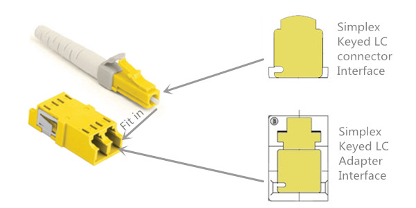
keyed-lc-connector-and-adapter
For example, the above picture shows the interfaces of a keyed LC connector and adapter which have yellow color and a unique keying pattern to ensure that they only fit each other. It is clearly showed that the inside structures of the yellow adapter and connector are different from the standard ones and are not compatible with the standards ones. All the other yellow-color LC products including LC patch cable, LC adapter panel and LC cassette which have the same keying feature. In a keyed LC connectivity system, connections can be identified directly by their colors. If the color does not match, the keying feature will prevent the connector from carrying the signal.
Full Series Keyed LC Connectivity Products
Some vendor can provide up to 6, 8 or 10 different colored keyed LC connectivity products. In FS.COM, the keyed LC connectivity products are available in 12 different colors. The above picture shows the 12 different keying features that are identified by colors.
The keyed LC connectivity might be needed in any point of the fiber optic network. To satisfy these requirements and increase the cabling flexibility, a full series of keyed LC connectivity products are introduced in FS.COM, including keyed LC connector, keyed LC adapter, keyed LC patch cable, keyed LC adapter panel, keyed LC fiber optic cassette. The keyed LC adapters are keyed on both the front and back to prevent installation errors and avid a possible security breach. The keyed LC patch cords are offered in multimode 62.5/125 m, 50/125um and laser-optimized 50/125um for the most demanding network performance. They are offered in standard lengths of 2 m (6 ft.), 3 m (10 ft.) and 5 m (16 ft.). Other lengths and configurations may be offered as custom orders. Please note different providers might have different keying pattern, even their keyed LC products are in the same color.
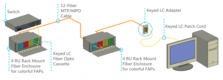
keyed-lc-connection-guide-768x275
How to Use Keyed LC Connectivity Product in Fiber Optic Network
The using of keyed LC connectivity products is not much different from the standard ones. However, they are much more easier for identification and management because of their color-identification system. The above picture shows a typical fiber optic link that is commonly deployed in today’s fiber optic network from data center switch to the target devices.
The keyed LC connectivity solution allows manageable and easily identifiable network segregation by use of a range of physically unique keyed connector and adapter combinations. Each color features a unique keying pattern that only allows matched color mating. As the leading fiber optical manufacturer in China, FS.COM offers keyed LC connectivity products, including keyed LC patch cables, secure keyed LC adapter panels, keyed LC connectors and so on. Other types of high quality fiber cables like SC SC patch cord, SC ST patch cord are also available for your choice.

2016年6月17日星期五

Why 40G Active Optical Cables So Popular?

Nowadays, 40 Gigabit Ethernet is the main trend in higher data transmission. The 40G optical devices are gaining popularity, including 40G QSFP+ transceivers and 40G direct attach cables. 40G direct attach cable (DAC) provides a cost-effective solution for high-density network connectivity. It is a kind of high-speed cable which has transceivers on either end used to connect switches to routers or servers. According to the media type, DAC can be classified into direct attach copper cable and active optical cable.
40G active optical cable (AOC) is a type of active optical cable for 40GbE applications that is terminated with 40GBASE-QSFP+ on one end, while on the other end, besides QSFP+ connector, it can be terminated with SFP+ connectors, LC connectors, etc. 40G active optical cables have great advantages over 40G direct attach copper cables (like QSFP+ cable) when transmission distance reaches up to 7 meters. Moreover, 40G AOC has lower weight and tighter bend radius, which enables simpler cable management.
40G AOC
Actually, 40GBASE-SR4 QSFP+ transceivers also have the above advantages. So why we highly recommend 40G AOC rather than 40GBASE-SR4 QSFP+ optics? The following section will tell the answer.
Firstly, 40G AOC has lower cost than 40GBASE-SR4 QSFP+ modules and does not need to use with extra fiber patch cables. Especially, 40G breakout active optical cables, such as 40GBASE QSFP+ to 8 x LC or 40GBASE QSFP+ to 4 x SFP+ are cost-effective solutions to achieve 40G migration. What’s more, if using AOC, there will be no cleanliness issues in optical connector and there is no need to do termination plug and test when troubleshooting, which can help end users save time and money.
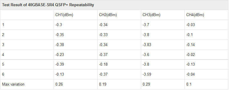
Insertion loss and return loss are the second factor. Under the same case of transmission distance, the repeatability and interchangeability performances of 40GBASE-SR4 module interface are not good as 40G AOC. Furthermore, when different fiber optic cables plug into the module, it will have the different insertion loss and return loss. Even for the same module, this issue is existed. Of course, the related metrics, such as the testing eye pattern, will have no significant changes so long as the variation in and conformed to the scope. In contrast, an AOC with good performance is more stable and has better swing performance than SR4 modules in this situation. The following table shows the result of the repeatability test of SR4 module. From the data, it is clear to see that the repeatability performance of SR4 module is not stable.
repeatability-test-of-SR4-module
Thirdly, four-quadrant test, a testing under four combinations of input voltage and signal amplitude, is used to ensure the product to keep better performance even under the lowest and highest voltage and temperature situation. Four-quadrant test in wide temperature range is used to test MTP/MPO interface and optical cable of AOC to ensure them not to be melted in high temperature. Generally, the current products of AOC can satisfy this demand. Moreover, the performance of AOC is more stable than SR4 module which should be used with indeterminacy-performance MTP/MPO connectors. Unlike 40GBASE-SR4 module, the quality index of AOC is judged by electric eye pattern but not by light eye pattern.
Fourthly, digital diagnostic monitoring (DDM) can help end users to monitor real-time parameters of the modules. Such parameters include optical output power, optical input power, temperature, laser bias current, and transceiver supply voltage, etc. 40GBASE-SR4 QSFP+ transceiver with DDM function can ensure its optimal coupling by the ADC (analog to digital converters) value of real-time monitoring receiver when receive coupling. Thus, 40GBASE-SR4 modules have better receiving sensitivity than 40G AOC. However, at present, the 40GBASE-SR4 and AOC cannot reach the function of real-time power monitoring.
Transmission distance is the last factor. When transmitting over OM3 fiber, there is no significant difference between 40GBASE-SR4 and 40G AOC. But 40GBASE-SR4 has better performance control than 40G AOC. Moreover, proposals for transmission distance that is longer than 300 meters will be SR4 module in order to ensure a good performance.
Through the above analysis, we can see that 40G AOC has better consistency and repeatability cabling performance. Moreover, it can avoid the influence of environment and vibration, even for troubleshooting, AOC is more easier to manage. So active optical cable is highly recommended to use in data center interconnection. Apart from 40G AOC, FS.COM also supplies 10G DAC (eg. SFP-H10GB-ACU10M) which can meet the ever increasing need to cost-effectively deliver more bandwidth, and can be customized to meet different requirements.

2016年6月7日星期二

Simplex and Duplex Fiber Optic Patch Cable Overview

When talking about fiber optic patch cable, related products that initially come into our mind are single mode and multimode fiber patch cable. However, there are still many other relevant terminologies such as multimode duplex LC LC cable, LC to LC duplex single mode patch cable and single mode simplex cable. For those who are new in this field, there is still much confusion about them. This paper will introduce simplex fiber patch cable and duplex fiber patch cable. In order to have a better understanding of simplex and duplex fiber optic patch cable, the definition of simplex and duplex will be explained in the first part.
What Do Simplex and Duplex Mean?
According to the ITU-T definition, a simplex circuit is one where signals can flow in only one direction at a time. One end is the transmitter, while the other is the receiver and that is not reversible. For example, in TV, audio or visual information flows from transmitter to numerous receivers.
However, at other times, communications can flow in the reverse direction. That is half-duplex. Half-duplex system means a communication channel that operates in one direction at a time and may be reversible. A good analogy for half-duplex system will be two roads with a traffic controller at each end, in order to ensure smooth flow of traffic, the traffic controller only allows one direction at a time. But if one party transmits at the same time, a collision occurs, resulting in lost messages.
simplex-duplex-fiber-optic-patch-cable
“Duplex” comes from “duo” that means “two”, and “plex” refers to “weave” or “fold”. A duplex system has two clearly defined paths with each path providing information in only one direction, that is A to B over one path, B to A over the other. Compared with half-duplex, a full-duplex system, or sometimes called double-duplex allows communication in both directions and allowing this to happen simultaneously. Just like the cellphone, both parties can speak and be heard at the same time.
Simplex vs Duplex Fiber Optic Cables
Simplex fiber optic patch cable consists of a single strand of glass fiber, and is used for applications that only require one-way data transfer. It is commonly used where only one single transmit and receive line is desired. Simplex fiber optic patch cable is available in single mode and multimode. For instance, a single mode simplex fiber patch cable is a great option for data travelling in one direction over long distance.
Duplex fiber optic patch cable consists of two strand fibers of glass structured in a zipcord arrangement where each fiber strand has independent coatings that are linked together by a thin layer of coating material. Duplex fiber patch cable is most used where separate transmit and receive signals are required, that is, one strand transmits in one direction while the other strand transmits in the opposite direction. It is available in single mode and multimode. Multimode duplex fiber optic patch cable or single mode duplex fiber optic patch cable is usually used for applications that require simultaneous and bi-directional data transfer. For example, 10 gigabit multimode duplex cables can support 10 Gb/s bandwidth in both directions within a short distance. LC to LC duplex single mode fiber patch cable can make simultaneous data transfer with LC-LC connectors over long distance.
Conclusion
Through the above analysis, do you have a clearer understanding of simplex fiber patch cable and duplex fiber patch cable? When choosing one over the other, the key factor is that the equipment requires one-way or bi-directional data transfer. FS.COM supplies numerous types of simplex and duplex fiber optic patch cables (or fiber jumpers), such as single mode simplex fiber patch cable, LC to LC duplex single mode patch cable, 10 gigabit multimode duplex cables, LC ST duplex patch cord and so on. I believe you can always find a suitable fiber optic patch cable for your devices here.

2016年6月2日星期四

With OM3, Will OM4 Still Be Needed?

With the transmission of massive amount of data, there is an increasing demand for higher bandwidth and fast speeds. The basic structure of network—cabling should be upgraded accordingly to meed this demand. For instance, copper cabling is developed from Category 1 to Category 8 cable. Likewise, fiber optic cabling also has its improvement, especially the multimode fibers that have OM1, OM2, OM3 and OM4 cables. OM1 specifies 62.5-micron cable and OM2 specifies 50-micron cable, while OM3 and OM4 are the optimized upgrade of OM2 for higher bandwidth applications, such as 40/100 GbE. However, a lot of confusion has emerged as the use of OM3 and OM4 fiber coexist. OM3 and OM4 seem to have many similarities and same applications. So why do we still need OM4 though we have already had OM3?
Similarities of OM3 and OM4
Both OM3 and OM4 are laser-optimized multimode fiber (LOMMF) and were developed to accommodate faster networks such as 10, 40 and 100 Gbps. They have the same fiber core size 50/125 and the termination of the connections is the same. Moreover, both of them are designed for use with 850nm VCSELS (vertical-cavity surface-emitting lasers) and have aqua sheaths. The picture below is a 10G OM4 SC LC fiber patch cable.
SC LC fiber patch cable
Difference Between OM3 and OM4
With the better fiber cable construction, OM4 fiber (4,700 megahertz) operates at higher bandwidth than OM3 (2,500 megahertz). The higher bandwidth available in OM4 refers to a smaller modal dispersion and thus allows for longer cable links or higher losses through more mated connectors. This provides more options when looking at network design. Besides, OM4 cable has better attenuation that leads lower losses than OM3. The lower losses mean that we have longer links or have more mated connectors in the link.
Actually, the factors that we describe above translate to longer transmission distances for the OM4 fiber. Although OM3 and OM4 can be both applied to 10GbE, 40GbE and 100GbE applications, they have different transmission distance. For 10G network, OM3 can transmit 300 m, while OM4 can transmit 500 m. For 40G and 100G network, OM3 supports 100 m, but OM4 supports 150 m. So OM4 has a better performance than OM3 due to its better cable construction. The primary cost increase of OM4 arises from this. The cost for OM4 is greater due to the manufacture process. Generally, OM4 cable is about twice as expensive as OM3 cable.
OM4 is a laser-optimized, high bandwidth 50 micrometer multimode fiber. In August of 2009, TIA/EIA approved and released 492AAAD, which defines the performance criteria for this grade of optical fiber. It can be used to enhance the system cost benefits enabled by 850 nm VCSELs for the earlier 1 G and 10 Gb/s applications as well as the 40 and 100 Gb/s systems. For example, most of ST to LC fiber jumper from FS.COM is manufactured using laser-optimized, 50/125, OM4 multimode cable, and can achieve max link distance of 50 meters. OM4 fiber can support Ethernet, Fibre Channel, and OIF applications, allowing extended reach upwards of 550 meters at 10 Gb/s for ultra long building backbones and medium length campus backbones. OM4 fiber is also especially well suited for shorter reach data center and high performance computing applications.
Except cost consideration, the availability of standard is the other consideration on using OM3 or OM4. OM3 is much more widely used than OM4 because there is a greater range and depth of standard product available. However, for factory manufactured pre-terminated solutions, the availability is now similar due to the increase in the demand for 40 GbE and 100 GbE. Additionally, OM3 and OM4 are completely compatible. So it is completely viable to mix OM3 product with OM4 and still obtain the required performance.
Conclusion
It is important to note that OM4 glass is not necessarily designed to be a replacement for OM3. Despite the relatively long-standing availability of OM4, there are no plans to obsolete OM3 fiber optic cabling. For most systems, OM3 glass is sufficient to cover the bandwidth needs at the distances of the current installation base. Most system requirements can still be reliably and cost effectively achieved with OM3, and this glass type will remain available for the foreseeable future. Despite the availability of OM4 glass, OM3 is quite capable of 40 and 100 Gb/s applications albeit at significantly shorter distances than OM4. This is why we need OM4 though we have already had OM3. All in all, which one to choose should depend on the network/distance design and cost as well as the future migration plan of your network.

2015年9月11日星期五

Introduction of Fiber Optic Patch Cord

A fiber optic patch cord is a fiber optic cable capped at either end with connectors that allow it to be rapidly and conveniently connected to CATV, an optical switch or other telecommunication equipment. Its thick layer of protection is used to connect the optical transmitter, receiver, and the terminal box. Fiber optic patch cords are characterized by low insertion loss, high return loss, good repeatability, good interchange and excellent environmental adaptability.
Construction
A fiber optic patch cord is constructed from a core with a highrefractive index, surrounded by a coating with a low refractive index, that is strengthened by aramid yarns and surrounded by a protective jacket. Transparency of the core permits transmission of optic signals with little loss over great distances. The coating's low refractive index reflects light back into the core, minimizing signal loss. The protective aramid yarns and outer jacket minimizes physical damage to the core and coating.
Size
Ordinary cables measure 125 µm in diameter (a strand of human hair is about 100 µm ). The inner diameter measures 9 µm for single-mode cables, and 50/62.5 µm for multi-mode cables. The development of "reduced bend radius" fiber in the mid-2000s, enabled a trend towards smaller cables. Each unit of diameter reduction in a round cable produces a disproportionate corresponding reduction in the space the cable occupies.
Classification
Patch cords are classified by transmission medium (long or short distance), by connector construction and by construction of the connector's inserted core cover. They can be classified as followings.
1. Transmission medium
According to transmission medium, fiber optic patch cord can be classified as single-mode (as the first picture below) and multi-mode (as the second picture below). Single-mode fiber is generally yellow, with a blue connector, and a longer transmission distance. Multi-mode fiber is generally orange or gray, with a cream or black connector, and a shorter transmission distance.
single-mode cable
multi-mode cable
2. Connector construction
Connector design standards include FC, SC, ST, LC, MTRJ, MPO, MU, SMA, FDDI, E2000, DIN4, and D4. Cables are classified by the connectors on either end of the cable. Some of the most common cable configurations include FC-FC, FC-SC, FC-LC, FC-ST, SC-SC, and SC-ST.
3. Inserted core cover
According to the construction of the connector's inserted core cover, fiber optic patch cord can be classified into APC, UPC, and PC configuration. A UPC inserted core cover is flat and is used in SARFT and early CATV. An APC connector's inserted core cover is oblique (about 30°, ±5°). Industry standard is a minimum of – 40dB for PC back reflection measurement and – 50dB for UPC back reflection measurement. If even less back reflection is required, an APC might be necessary. An APC connector has an 8ºangle cut into the ferrule. These connectors are identifiable by their green color. An APC polished connector has an industry standard minimum of – 60dB measurement. APC fiber ends have low back reflection even when disconnected.
Applications
Patch cables are widely used for connections to CATV (Cable Television), telecommunication networks, computer fiber networks and fiber test equipment. Applications include communication rooms, FTTH (Fiber to The Home), LAN (Local Area Network), FOS (Fiber Optic Sensor), fiber optic communication system, optical fiber connected and transmitted equipment, defense combat readiness, etc.
Fiber optic patch cord plays an important role in fiber communication industry, thus getting more knowledge of fiber optic parch cord is necessary for all people in this industry. This article helps us know better of fiber optic patch cord from construction, classification, size, applications and so on.

2015年9月10日星期四

Introduction to Optical Fiber Cable

An optical fiber cable is a cable containing one or more optical fibers that are used to carry light. The optical fiber elements are typically individually coated with plastic layers and contained in a protective tube suitable for the environment where the cable will be deployed. Optical fibers are widely used in fiber-optic communications, where they permit transmission over longer distances and at higher bandwidths (data rates) than wire cables. This article helps us know more of fiber cable from different aspects, such as design, reliability and quality, cable types and so on.
Design
In order to protect fiber from damage, there are different applications of optical fibers according to different environment. For indoor applications, the jacketed fiber is generally enclosed, with a bundle of flexible fibrous polymer strength members like aramid, in a lightweight plastic cover to form a simple cable. For use in more strenuous environments, a much more robust cable construction is required. In addition, a critical concern in outdoor cabling is to protect the fiber from contamination by water. Finally, the cable may be armored to protect it from environmental hazards, such as construction work or gnawing animals.
Modern cables come in a wide variety of sheathings and armor, designed for applications such as direct burial in trenches, dual use as power lines, installation in conduit, lashing to aerial telephone poles, submarine installation, and insertion in paved streets.
Reliability and Quality
Optical fibers are very strong, but the strength is drastically reduced by unavoidable microscopic surface flaws inherent in the manufacturing process. The initial fiber strength, as well as its change with time, must be considered relative to the stress imposed on the fiber during handling, cabling, and installation for a given set of environmental conditions. There are three basic scenarios that can lead to strength degradation and failure by inducing flaw growth: dynamic fatigue, static fatigues, and zero-stress aging.
Cable Types
OFC: Optical fiber, conductive
OFN: Optical fiber, nonconductive
OFCG: Optical fiber, conductive, general use
OFNG: Optical fiber, nonconductive, general use
OFCP: Optical fiber, conductive, plenum
OFNP: Optical fiber, nonconductive, plenum
OFCR: Optical fiber, conductive, riser
OFNR: Optical fiber, nonconductive, riser
OPGW: Optical fiber composite overhead ground wire
ADSS: All-Dielectric Self-Supporting
Fiber Material
There are two main types of material used for optical fibers. These are glass and plastic. They offer widely different characteristics and therefore fibers made from the two different substances find uses in very different applications.
Color Coding
Individual fibers in a multi-fiber cable (as the picture below) are often distinguished from one another by color-coded jackets or buffers on each fiber. The identification scheme used by Corning Cable Systems is based on EIA/TIA-598, "Optical Fiber Cable Color Coding." EIA/TIA-598 defines identification schemes for fibers, buffered fibers, fiber units, and groups of fiber units within outside plant and premises optical fiber cables. This standard allows for fiber units to be identified by means of a printed legend. This method can be used for identification of fiber ribbons and fiber sub-units.
multi-mode cable
Capacity and Market
Modern fiber cables can contain up to a thousand fibers in a single cable, with potential bandwidth in the terabytes per second. In some cases, only a small fraction of the fibers in a cable may be actually "lit". So they have a big market in fiber optic industry. For example, companies can lease or sell the unused fiber to other providers who are looking for service in or through an area.

2015年9月9日星期三

Fiber Optic Transceivers

Fiber optic transceivers consist of a transmitter on one end of a fiber and a receiver on the other end. The transmitter takes an electrical input and converts it to an optical output from a laser diode or LED. The light from the transmitter is coupled into the fiber with a connector and is transmitted through the fiber optic cable plant. The light from the end of the fiber is coupled to a receiver where a detector converts the light into an electrical signal which is then conditioned properly for use by the receiving equipment.
Sources For Fiber Optic Transmitters
The sources used for fiber optic transmitters need to meet several criteria: it has to be at the correct wavelength, be able to be modulated fast enough to transmit data and be efficiently coupled into fiber. Four types of sources are commonly used, LEDs, fabry-perot (FP) lasers, distributed feedback (DFB) lasers and vertical cavity surface-emitting lasers (VCSELs).
There are many differences between LEDs and lasers. Firstly, LEDs have much lower power outputs than lasers and their larger, diverging light output pattern makes them harder to couple into fibers, limiting them to use with multi-mode fibers, while lasers are on the contrary. Secondly, LEDs have much less bandwidth than lasers and are limited to systems operating up to about 250 MHz or around 200 Mb/s. Lasers have very high bandwidth capability, most being useful to well over 10 GHz or 10 Gb/s. Thirdly, because of their fabrication methods, LEDs and VCSELs are cheap to make. Lasers are more expensive. Fourthly, LEDs have a limited bandwidth while all types of lasers are very fast. Moreover, LEDs have a very broad spectral output, while lasers have a narrow spectral output that suffers very little chromatic dispersion.
The choice of these devices is determined mainly by speed and fiber compatibility issues. As many premises systems using multi-mode fiber have exceeded bit rates of 1 Gb/s, lasers (mostly VCSELs) have replaced LEDs. The output of the LED is very broad but lasers are very focused, and the sources will have very different modal fill in the fibers. The restricted launch of the VCSEL (or any laser) makes the effective bandwidth of the fiber higher, but laser-optimized fiber, usually OM3, is the choice for lasers.
Detectors For Fiber Optic Receivers
The electronics for a transmitter are simple. They convert an incoming pulse (voltage) into a precise current pulse to drive the source, while receivers use semiconductor detectors to convert optical signals to electrical signals. Silicon photodiodes are used for short wavelength links. Long wavelength systems usually use InGaAs detectors as they have lower noise than germanium which allows for more sensitive receivers.
Transceivers Packaging
As to the packaging, transceivers are usually packaged in industry standard packages like these XFP modules (as the picture below) for gigabit data links(L) and Xenpak (R). The XFP modules connect to a duplex LC connector on the optical end and a standard electrical interface on the other end. The Xenpak are for 10 gigabit networks but use SC duplex connection. Both are similar to media converters but are powered from the equipment they are built into.
XFP modules
From this article, we can know better of fiber optic transceivers from the following aspects: sources for fiber optic transmitters, detectors for fiber optic receivers, and transceivers packaging. As the rapid development of fiber optic communication industry, fiber optic transceivers are playing an increasingly important role in modern communication.